Development of a Novel Engine Test Rig for Research and Educational Purposes. A group of very talented future mechanical engineers asked to come to Weistec Engineering for their senior design project, and of course we were more than happy to accomodate.
Using our latest in digital 3D scanning capabilities, our expertise in design software, and our machining capabilities, our engineers were ready to take these creative students to the next level with their Wave Disk Engine design.
Over the last three years, a senior elective course entitled “Turbomachinery” has been developed and offered at the EMET department to introduce undergraduate students to the fundamentals of turbomachinery and cultivate understanding of the working principles of rotary devices.
Cal Poly Pomona is one of 23 campuses of the California State University system. The campus currently enrolls more than 23,000 undergraduates and 1,600 graduate students. Each year approximately 650 students graduate from seven individual departments at the College of Engineering. Electromechanical Engineering Technology (EMET) Department as one of the undergraduate engineering programs incorporates theory and practice in a learning-centered environment. The EMET program prepares students for careers in industry and emphasis is placed on application of engineering principles in solving real world problems. Successful students after graduation often find various opportunities in manufacturing, design, and many other related areas.
All in all, it was a great success! Strong engineering is the foundation of Weistec, it's what lead us to success. Welcoming students to use our facility was an absolute pleasure for us and look forward to bright young minds touring our facility again.
Paper ID #27809
Development of a Novel Engine Test Rig for Research and Educational Purposes
Prof. Pejman Akbari, California State Polytechnic University in Pomona
Dr. Pejman Akbari is an assistant professor at California State Polytechnic University in Pomona with over a decade of experience and expertise in utilizing unsteady flows for advanced propulsion and power generation systems. His education includes a Postdoctoral Research position at Purdue School of Engineering and Technology in Indianapolis (2004-2006), B.S. (1996) and M.S. (1998) degrees in Aerospace Engineering, and a Ph.D. (2004) in Mechanical Engineering from Michigan State University. Dr. Akbari is the author of over 50 peer-reviewed journals/papers and 3 patents related to nonsteady-flow devices.
Mr. Brad Kevin Thomas, Electro Mechanical Systems Engineering Technology
Born and raised in Chino, CA and with a Bachelors Degree from California Polytechnic Pomona, Brad Thomas has alway been interested in anything mechanical as well as engines. Brad stays busy working on and building engines for all kinds of cars, motorcycles and even boats as well as enjoying time with friends and family.
Mr. Christopher John Tait, Cal Poly Pomona
Christopher (CJ) Tait obtained his Bachelor’s Degree in Electromechanical Systems Engineering Technology from California State Polytechnic University, Pomona in June 2018. During his senior year at Cal Poly Pomona, CJ contributed to the design and manufacturing of the Radial Wave Engine. After graduation, he worked as a Research Engineer testing the Radial Wave Engine at the Air Force Research
Laboratory in Dayton, Ohio. Continuing his career in the Aerospace industry, CJ works as a Design Engineer at HiRel Connectors, Inc.
Abstract
This paper overviews a senior design project conducted by three undergraduate engineering students at California State Polytechnic University in Pomona (Cal Poly Pomona), aimed at developing a small-scale test bed facility to support ongoing research on the subject of novel engines, as well as enhancing academic education. The project received support from a local industrial company (Weistec Engineering) and the U.S. Air Force Institute of Technology. The paper reports how the idea was conceived from design concept to manifestation of a demonstrator engine through detailed planning and significant team efforts. The paper describes the planning and implementation process including required course development, securing funding for the research, and student involvements in the design process, construction and assembly, initial testing, lessons learned, and plans for future work. The project’s approach could be adapted to projects in any engineering discipline. Reporting this journey aims to stimulate interest among academic faculty and students in pursuing comparable endeavors and taking advantage of available resources offered by academia, industry, and the government.
Background
Since the invention of jet engines, the attention of engine designers has been mainly focused on employing steady-flow principles for various engine components. Meanwhile, oscillatory and pulsatile fluid motions commonly observed in nature are often neglected by engineers due to their complexity.1 By understanding and exploiting complex unsteady flows a significant increase in engine performance is possible.2 It appears feasible to simplify the hardware of engines, making them less costly, more compact, more responsive, and more durable by employing unsteady processes.
In 2003, a patent was filed by Müller et al. at Michigan State University (MSU) entitled “Wave Rotor Apparatus” 3 introducing a novel unsteady combustion engine configuration used for stationary power generation units and automobile engines. The proposed engine, the Wave Disk Engine, is described as a radial-shape engine concept which has potential for higher power density, and is expected to provide a significant reduction in engine size, manufacturing costs, and specific fuel consumption for future power-generation systems.4 After initial numerical 5 and analytical 6 investigations, the concept gradually evolved into a small size proof-of-concept demonstrator which was tested in 2010-2012 to be used as a backup generator in a hybrid car.7 The prototype engine had only one moving part and all three processes of compression, combustion, and gas expansion would occur within a single spinning rotor. Instead of employing a commonly used compressor for compression, the reactant was pressurized by a “hammer shock” created inside the spinning combustion chambers and power output was produced through the expansion of the highpressure burned gases within the rotating disk. While the MSU prototype engine represented a novel work-producing combustor and demonstrated the engine concept, it yielded low thermal efficiency and did not produce targeted power. Because the only moving component was the rotor, the power output only relied on torque generated by the blades. With limited size of the channel, the test results revealed that it was not possible to fully expand burned gases. A considerable amount of thermal and pressure energy available in the products was wasted to the surroundings after discharging of the burned gases to the atmosphere in addition to excessive flow leakage without using a seal between the rotating blades and the outer casing. By the end of the program in 2012, a new design utilizing an external turbine was proposed and patented by Müller et al. 8
suggesting an effective technique to benefit from the available energy in the exit flow. Despite promising features of this proposal, Müller’s team did not build the proposed design mostly due to lack of funding. Within a few years, a team of researchers at Cal Poly Pomona made a risky decision to investigate the new design. Many challenges existed which needed to be addressed such as absence of graduate students, lack of external research grant and a testing facility at campus. In the following, it is described how these difficulties were overcome and how the project was successfully conducted.
Electromechanical Engineering Technology Department at Cal Poly Pomona
Cal Poly Pomona is one of 23 campuses of the California State University system. The campus currently enrolls more than 23,000 undergraduates and 1,600 graduate students. Each year approximately 650 students graduate from seven individual departments at the College of Engineering. Electromechanical Engineering Technology (EMET) Department as one of the undergraduate engineering programs incorporates theory and practice in a learning-centered environment. The EMET program prepares students for careers in industry and emphasis is placed on application of engineering principles in solving real world problems. Successful students after graduation often find various opportunities in manufacturing, design, and many other related areas. After completing core courses, the EMET students are eligible and required to take a few elective courses during their junior and senior years. These elective courses are specifically designed to help the students develop skills that are of use to industry. In other words, the elective courses offer opportunities to capture the interest of the students and help them make a step towards their desired careers. In such upper-year engineering courses, students are challenged on their preexisting knowledge and learn to develop critical thinking on various engineering topics. Next, it is explained how an elective course was developed and offered at the EMET department to support the reported research here.
Elective Course: Turbomachinery
Over the last three years, a senior elective course entitled “Turbomachinery” has been developed and offered at the EMET department to introduce undergraduate students to the fundamentals of turbomachinery and cultivate understanding of the working principles of rotary devices. The intention behind creating this course includes training a group of students who can contribute to the ongoing research at Cal Poly Pomona related to the field of energy, as well as preparing students for gas-turbine job opportunities in industry. An average of 30 students often take the course each year in the fall semester. Course prerequisites include Applied Thermodynamics and Applied Fluid Mechanics. Turbomachinery is a lecture-based course (i.e. no laboratory component) and the students meet with the instructor for 1.15-hour lectures twice per week. In this introductory course, after students become familiar with existing turbomachinery devices such as pumps, compressors, and turbines, they develop knowledge about the preliminary design methodology and design considerations for each device. The course is aimed at thermal-fluid aspects of turbomachinery components, and students are encouraged to learn about other topics such as rotor dynamics from available references and resources provided to them. One of the major challenges identified during the course is that students are less familiar with compressible-flow theories/concepts which are usually not discussed in depth in the previous thermal-fluid courses. It is also recognized that the introduction of laboratory experiments can help the students to better
visualize complex blade shapes discussed in the course. However, purchasing and implementation of turbomachinery experiments are very expensive and require appropriate space and facilities. It is a fact that while many engineering schools offer a course in turbomachinery, not all have the capacity to provide hands-on experience through running experiments. Consequently, only a handful of research universities in the nation have been able to provide turbomachinery laboratory experiences to their students. Instead, currently the students are offered a couple of visits to facilities where they can observe turbomachinery devices, linking the theoretical information they gain in the classroom to a practical turbomachinery set up. Positive feedback has been reported by the students and after each visit the students have a better understanding of the materials discussed in the lectures. Finally, students who successfully complete the course can potentially become qualified candidates to work with faculty members who conduct research in the field of turbomachinery.
Senior Design Project
For students entering their senior year, it is common among engineering programs in the nation and worldwide to participate in senior design group activities. These activities are prominent elements of engineering degree programs and are critical to the development and assessment of students’ professional skills for their earned degrees. They provide a unique opportunity for students to work together on a hands-on project in a timely fashion and develop their engineering skills by solidifying much of what is learned in the classroom. Additionally, executing a senior design project improves their technical knowledge, as well as their problem solving and communication skills. Prior to Fall 2018, the academic year at Cal Poly Pomona was divided into three periods of ten weeks (quarter-based system). At the EMET department, senior project was carried out in teams of typically three undergraduate students over three full quarters (30 weeks total). On average, 5- 10 hours per week on the project for the academic year was expected. The process would start at the beginning of the fall quarter, when students were encouraged to either brainstorm interesting ideas of their own or approach faculty members to learn about their suggested topics. After the students had the opportunity to review the available projects, each group was asked to select and work on two different project ideas simultaneously. Within the remaining weeks of the quarter they would evaluate these two projects. By end of the first quarter, students prepared a written report for each topic and conducted an oral presentation of the overall results to their classmates and the faculty members involved in the course. Once the final project was selected, during the consequent quarters, each group supervised by a faculty advisor would start the design process. The groups would meet the project milestones and design/build a final product in the form of a prototype device within the limits of their budget. By the end of the academic year, each group would hand in a detailed report to include details of the design procedure, its analysis and results, and recommendations for future work. Finally, the students would give a presentation to the general public describing the design process, the challenges encountered, results, lessons learned, and layout of their prototype. Senior design projects additionally allow the industries to identify potential talents for employment and recruiting benefits.
Strategic Interdisciplinary Research Grant Program
Building prototype components in turbomachinery can be very costly, and that is the main reason student senior design projects in turbomachinery do not often reach the stage of building the actual device. These projects are sometimes limited to 3D print using plastic material. We took advantage of a grant for research initiatives given by the Office of Research at Cal Poly Pomona to manufacture a test bed facility to be used for both research and educational purposes. The Cal Poly Pomona Strategic Interdisciplinary Research Grant (SIRG) Program is designed to promote interdisciplinary initiatives involving at least two departments and is given to proposals that are viewed as likely to result in major interdisciplinary research topics. Awards range from $10,000 to $25,000 per funded project. Usually 3 to 6 proposals are awarded per year. The proposed project received a budget of $15,000 to be used in the academic year 2017-2018 to design a RWE demonstrator. The SIRG was awarded due to the fact that our proposed engine project not only was a research project, but it was also intended to eventually add a new experiment for the existing Internal Combustion Engine Laboratory. The price for purchasing laboratory engine facilities from the market for educational activities is usually very high (well over $50,000) and beyond the department’s budget. Thus, the decision of designing and building a new engine facility at relatively low cost is financially very beneficial. The entire budget was invested in materials, tools, and construction of the test facility.
Rotating Wave Engine
The Rotating Wave Engine (RWE) does not operate like traditional internal combustion engines or gas turbine engines. In the following section, a brief description of the designed engine is provided to help the reader understand the working principles and advantages of this type of engine. The reader is referred to available references in the literature for more details and discussions.10-12
Motivation and Application
For transportation and aeropropulsion applications, it is advantageous to produce light weight, compact power generation units with high efficiency. Even for stationary distributed power generation, the choice of compact and efficient engines is attractive. The RWE is a pistonless rotary engine which has a spinning radial combustor in which constant volume combustion (i.e. pressure gain combustion) occurs using stationary inlet and exit end walls resembling a valvedcombustor. Power output is generated via a radial-outflow turbine forming a purely disk-shape engine. This new engine concept operates closely based on the most efficient thermodynamic cycle, the Humphrey cycle, combining constant volume combustion and complete expansion to achieve high efficiency compared to Otto, Diesel, and Brayton cycles.13 The proposed radial engine can be considered as a hybrid engine concept which midways between piston and turbine engines with improvements to other counterpart designs. The engine has unique potential for higher power density and is expected to provide a significant reduction in engine size, manufacturing costs, and specific fuel consumption for future power-generation systems. Efficient
power generation in various scales is in high demand, and the RWE working on the most efficient thermodynamic cycle could offer high efficiency with fewer moving parts and simpler fabrication. For instance, the introduced engine could be an ideal engine implemented in unmanned air vehicles for both military and civil missions. This engine may be alternatively used to create efficient electrical power, replacing batteries for compact mobile power generation units or hybrid automobiles.
How Does the RWE Work?
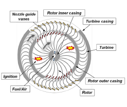
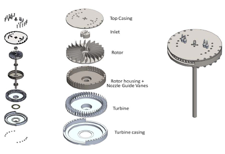
Figure 1 schematically illustrates the layout of a RWE with two operating cycles per one revolution. The core of the engine is a rotor with “on-rotor” combustion within its rotating channels. The shape and orientation of combustion channels vary depending on the application, for example by curving the rotating channels, it is possible to change the angular momentum of the flow and extract mechanical work from the rotor. Compressed premixed fuel/air mixture axially enters the center of the engine and is radially delivered to two annular inlet ports placed at the periphery of an inner casing termed as the inner end wall. The inner ports charge rotating channels when they meet the stationary ports. The channels are curved to change the angular momentum of the working flow and surrounded with a stationary outer casing denoted as the outer end wall. The outer casing includes two annular exit ports placed at its periphery. The channels rotate between the stationary inner and outer casings where the inlet and exit ports allow the flow to enter and exit the rotating channels. Therefore, the end walls function as contactless inlet and exit valves for individual rotating combustion chambers that periodically charge and discharge as they rotate past the inlet and exit ports. The device is designed in such a way that combustion is initiated shortly after both ends of the channel(s) are closed, generating a constant volume combustion where the mixture pressure and temperature are elevated significantly. Meanwhile, centrifugal force on the flow facilitates the flushing and loading processes. The high-pressure hot gases exiting the channels are directed to two-dimensional nozzle guide vanes mounted at the rotor exhaust ports. The nozzle guide vanes accelerate and deliver the burned gases to a two-dimensional cross-flow radial turbine with impulse-type blading mounted on the outer surface of the rotor casing. The turbine functions as a free power turbine to harness energy available in the exhaust gases in the form of mechanical shaft power. For a design with a centrifugal compressor embedded in the center of the engine (not shown), part of the turbine torque can be transmitted to the compressor through a shaft.
Design Process and Challenges
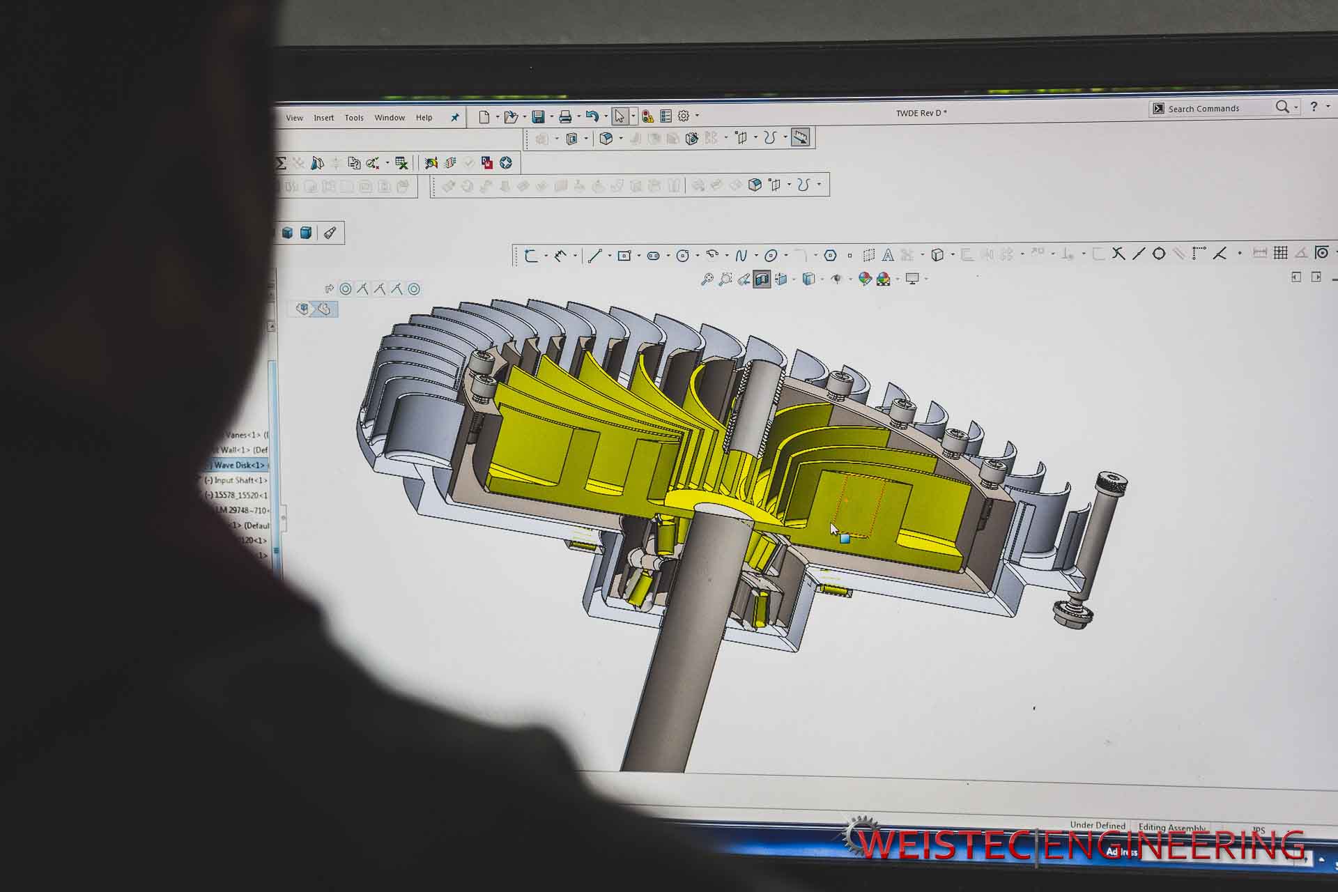
An ambitious project in design and manufacturing of a small-scale RWE test rig was introduced in the form of a senior design project for academic year 2017-2018. A team of three senior-year undergraduate engineering students at the EMSET program was formed at the beginning of Fall 2017 supervised by their faculty advisor. They were directed to complete the project in one academic year with a budget of $15,000 funded by the SIRG Program described earlier. The project required the students to put into practice their mechanical design and turbomachinery knowledge while practicing discipline, establishing deadlines, and displaying effective project management. The project was split into four phases, namely knowledge development, preliminary design, detailed design, and fabrication, spread over 30 weeks. During all these four phases, the faculty advisor interacted with the students frequently through weekly meetings to ensure the project was progressing in the right direction. For the initial phase, which covered the first month, the students learned about the RWE working principles by studying compressible-flow theories and previous conducted research by Müller et al. 7 and others.14 The students became aware of challenges and shortcomings of previous designs to make sure they would not repeat the same mistakes in their design. In the second phase, which covered two months, the team evaluated size and design requirements of the rig based on past practice by MSU’s team, geometrical constraints, and using analytical predictions to come up with a preliminary design. For instance, one-dimensional analytical design tolls were used to determine inlet/exit port sizes, rotor and turbine blade shapes, rotor speed, and selection of the required electric motor for the rotor shaft. Students had to use their knowledge and skills learned in thermal-fluid science and turbomachinery courses at this stage. In the third phase, detailed design, commercial software SolidWorks was used (see Fig. 2) to produce
computer models and precise drawings of all components including shafts, bearings, and couplings. The students made use of knowledge from the courses in computer modeling as well as courses in solid mechanics and machine design. This procedure took about three months and a series of modifications and re-drawings were made to refine the first design. Besides the team members and the upervising advisor, the design was discussed with experts in academia and industry for feedback and constructive suggestions. The design was refined according to the valuable feedback and recommendations. It is acknowledged that a structural analysis was not considered as the RWE rig was solely designed for short-term research purposes and not commercial usage at this time. In parallel with designing the engine, a list of required components and assembly units (materials, bearings, electric motor, spark plugs, coils, etc.) was identified and ordered after getting quotes from vendors. The role of advisor faculty was important in all these three phases.
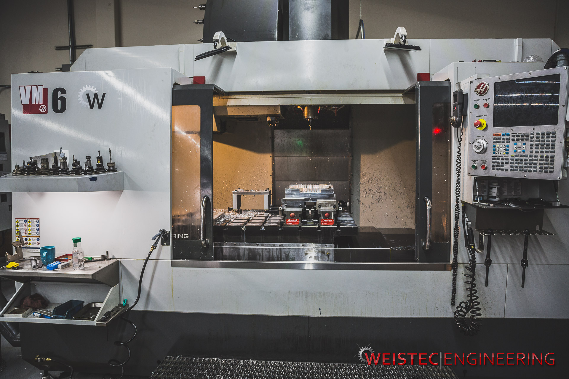
In the final phase, covering months three through nine, machining of engine parts was scheduled. The major challenge was finding a machine shop to manufacture the engine with high quality and precision within the budget constraints. Due to the complex geometries of the components, many programming and machining hours were required to manufacture the engine. The advice of several
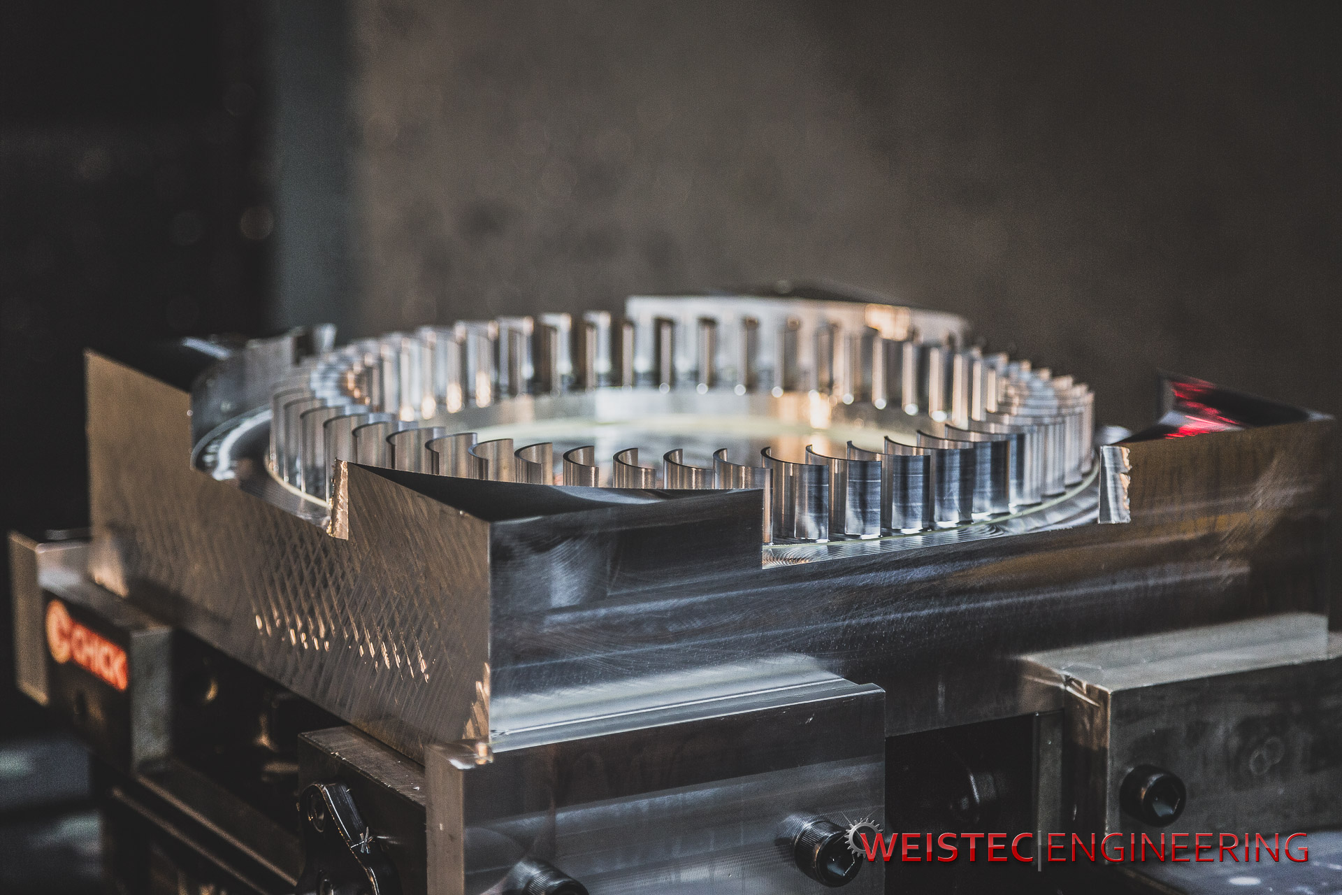
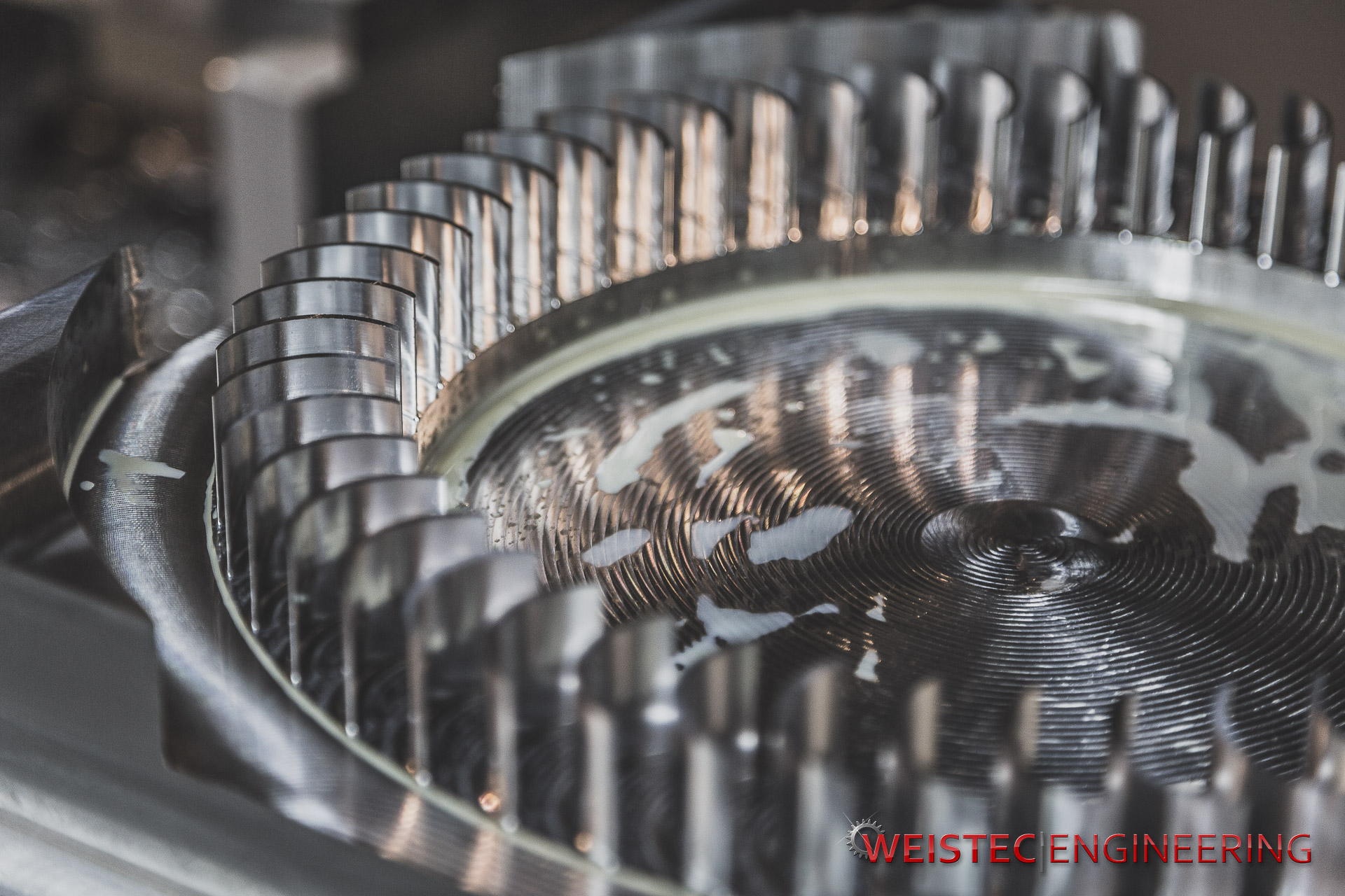
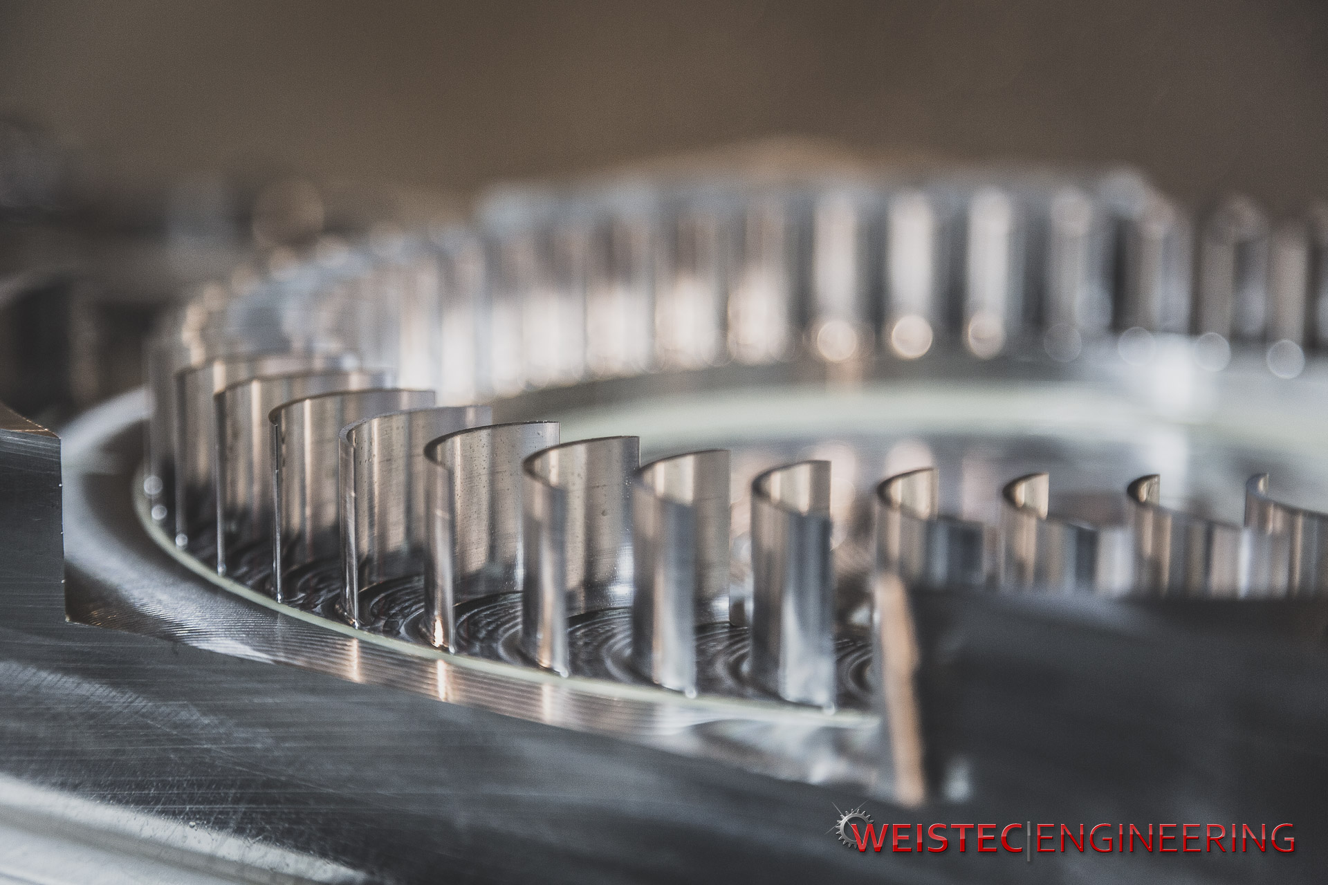
industry experts was sought when searching for a place to manufacture the engine. The team contacted and negotiated with many outside manufacturers. For most companies either their lead time was too long due to other orders that they had already accepted, or they would ask for manufacturing fees beyond the project budget. Finally, Weistec Engineering located at Anaheim California (http://www.Weistec.com) specializing in designing and engineering customized automotive parts, was selected. To support Cal Poly Pomona, the company owner generously offered to machine the parts at no cost, reducing the total cost of the project significantly. During the fabrication at Weistec Engineering, the students visited the company’s location to observe the manufacturing processes and discuss the specifics of the project with the industry experts. In each visit, the students had the opportunity to work alongside the experienced technician and receive feedback from mentors in the company to improve their design, resulting in a better understanding of implementing manufacturing techniques. Figure 3 captures moments when two team members were observing and taking advice from an experienced technician.
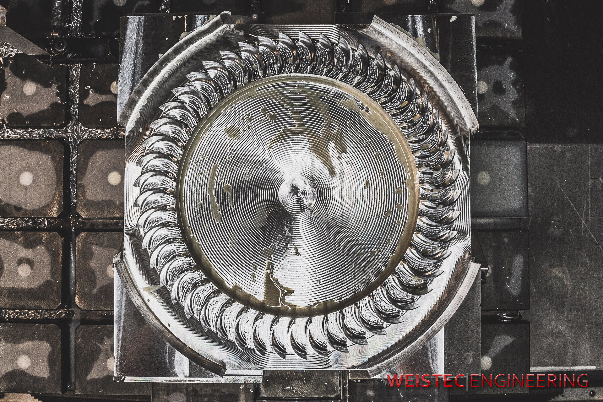
Manufacturing and Assembly Processes
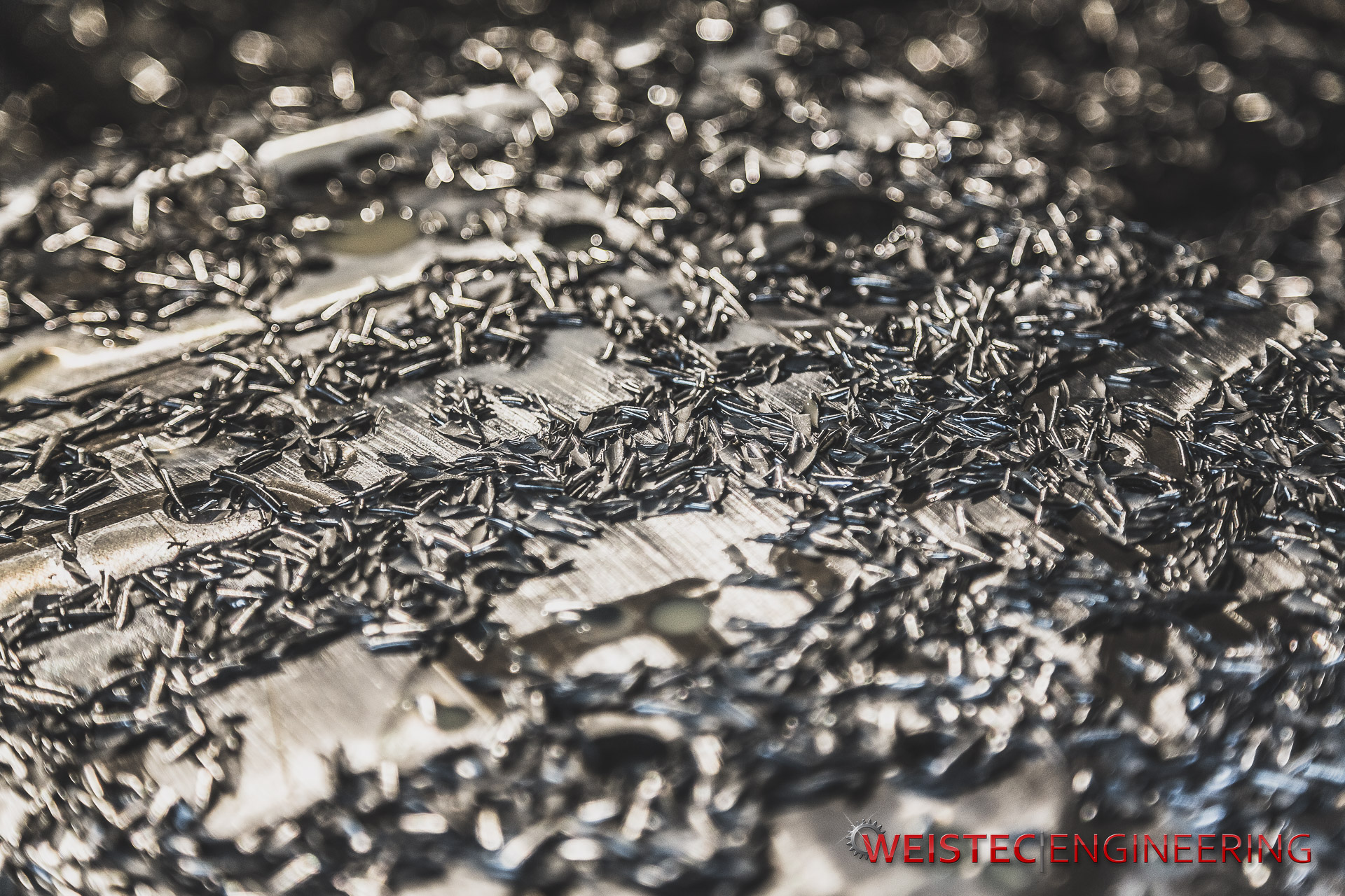
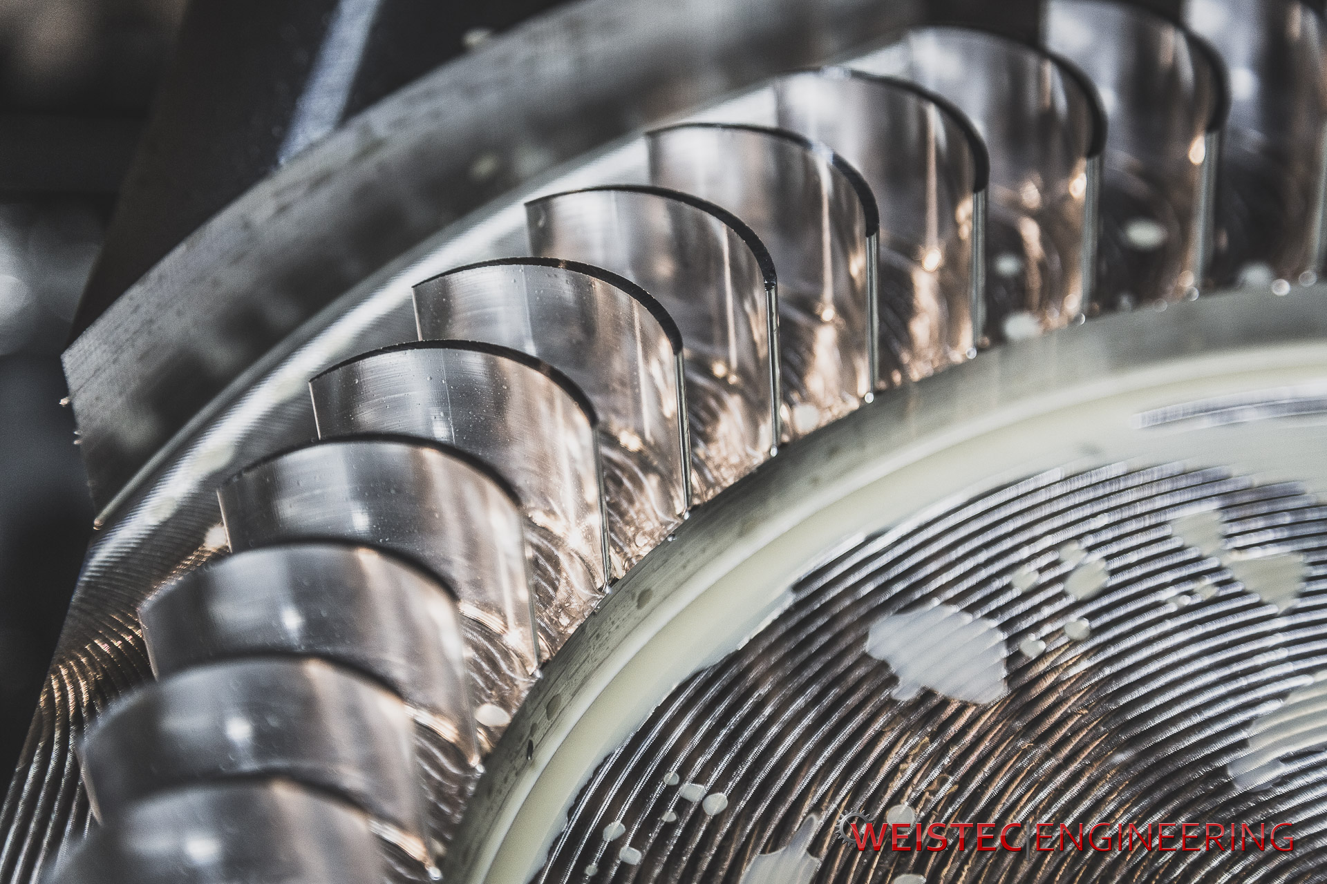
The engine components were fabricated using machining technology at Weistec Engineering. The material selection of different parts was largely based off the chosen manufacturing method, weight restriction, budget, and time frame of the project. For instance, if the components were going to be casted, then a nickel-based or iron-based alloy would be chosen. With standard machining, the material options included stainless steel, aluminum alloy, and nickel-based alloys. Stainless steel was used for major parts including the rotor blades, rotor shaft, rotor outer casing, and the top plate. To reduce time needed for machining time and fabrication, low-cost aluminum was used for the turbine blades/shaft/housing. It was recognized that the choice of metal was not optimal for a high-temperature environment, but due to thermal considerations the combustion tests were designed for only short durations (on the order of 2-3 seconds). The color difference of metals in Fig. 4 shows the different materials used for the rotor and turbine sections. By using aluminum as a compromise for the two largest pieces of the engine (turbine blades and turbine casing), the RWE total weight, cost, and machining time were cut down significantly. The RWE was designed to ensure each component was able to stack within the next subsequent part, allowing a more compact engine than an internal combustion engine or a gas turbine engine.
Concept Validation
To demonstrate the viability of any new engine concept, engine testing is necessary to produce experimental data that identify the key parameters impacting the operation and performance of the engine. However, experimental laboratory experience with engines is costly, especially when a testing facility equipped with instrumentations and safety equipment do not exist on campus. An alternative option, and perhaps the least costly, was to test the engine in a facility off campus. Because the entire research funding was already spent on the engine fabrication, no funds were available to secure another location test the engine. Meanwhile governmental agencies such as the U.S. Air Force, Navy, and Army offer opportunities for universities to promote their applied and fundamental research activities. The faculty advisor of the RWE project applied for the U.S. AirForce Research Lab Summer Faculty Fellowship Program (SFFP) which offers hands-on exposure to Air Force research laboratories for full-time science, mathematics, and engineering faculty at U.S. colleges and universities. In support of world-wide ongoing research in the field of ultraefficient gas turbines using pressure gain combustion technology, the fellowship was successfully secured and arrangements were made to test the engine in the Small Engine Research Facility located at Wright-Patterson Air Force Base during Summer 2018. Through negotiation efforts, one of the student members also received a summer internship by the U.S. Air Force to assist the faculty advisor with the combustion tests.
Operation of the RWE started with bringing the rotor to a particular speed and turning on fuel/air flow. Then, the spark plugs were engaged while the rotor continued to spin. At the design operating conditions (35.5 g/s flow at equivalence ratio of 0.5 and 2000 RPM) the engine operated smoothly throughout startup, ignition, and shutdown. The turbine spun at 21 RPM, validating that the engine could produce torque.
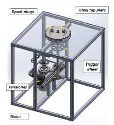
To inspect the flow behavior in the reaction zone occurring within the channels, the steel top casing was replaced with a transparent polycarbonate window. The optical window allows for observations and measurements of the angular distance traveled by the rotor during flame development. In the present study, a high-speed (Phantom) camera mounted on a tripod operating at 13,000 frames per second was used to capture flame propagation within the channels. Tests were completed successfully, and results have been reported in Ref. [15]. Project Outcomes and Future Work This paper summarized a hardware development project conducted by three senior students led by their faculty mentor at Cal Poly Pomona and presented the experience that was achieved by using this engine as a support for research and education. The conducted work was the first step to develop a revolutionary engine based on pressure gain technology that has unique potential for higher energy efficiency and power density of future power-generation systems. The RWE offers significant improvem